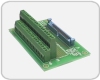
RELAYIO-104
Relay Output / Isolated Input Module for PC/104 Bus
Stock Number:
- 100-7610
Budgetary Pricing:
- $188.12 / 001 - 009
- $180.60/ 010 - 024
- $173.37 / 025 - 049
- $166.58 / 50+
- Contact us for More Quantity Discounts
Typical Lead-Time:
- Stock - 2wks

DESCRIPTION
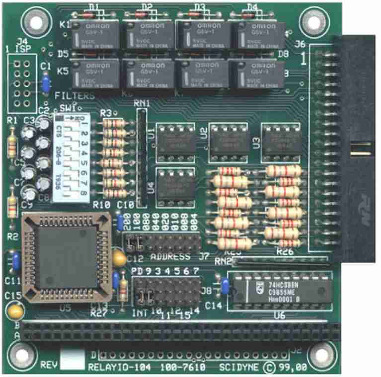
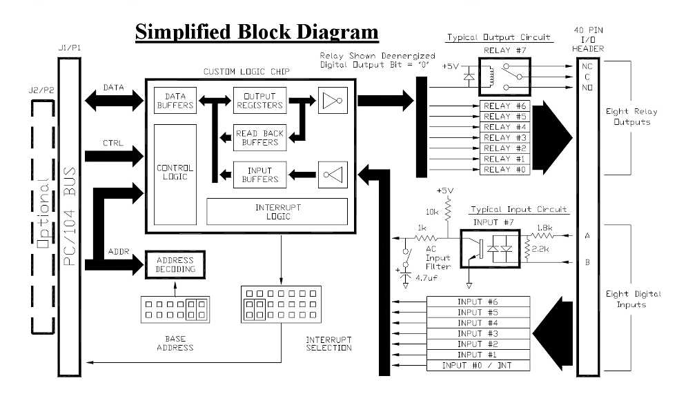
The RELAYIO-104 is an 8-bit digital I/O peripheral module offering electrical isolation between the host and externally connected devices. It conforms to the PC/104 standard and operates on a single +5V power supply. A 40-pin IDC ribbon connector is used for all external wiring.
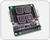
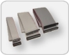
Relay Outputs
Eight SPDT (form C) relays are used for the digital outputs. Independent access to each relay's Normally-Closed, Normally-Open and Common terminals eases wiring constraints and permits flexible mixing of AC and DC signals. Each output is capable of controlling loads up to 1A @ 24Vdc or 0.5A @ 125VRMS. They also feature Break-Before-Make operation.
An 8-bit output register controls the state of the eight relays. By default, all relays are in a de-activated ( Normally-Closed ) state during power-off and system reset. A relay is activated by writing a "1" to its corresponding bit within the output register. Writing a bit as "0" de-activates the corresponding relay. The register is both readable and writable facilitating efficient Read-Modify-Write bit manipulations software techniques to be used.
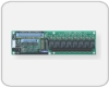
Optically Isolated Digital Inputs
Eight separate inputs using non-polarized optical isolators allow any combination of DC or AC signals to be monitored. Their wide input voltage range (3-24V) is suitable for a diverse range of applications. Each input has an associated low-pass filter that can be individually enabled for the reliable measurement of AC signals. The filter is especially helpful when monitoring noisy DC signals.
The on/off states of the inputs are held in an 8-bit read-only register. An activated input appears as a "1" in its corresponding bit position.
Digital Input #0 has the added capability of optionally generating a host interrupt the moment it becomes activated. The event is latched in an interrupt status register so that even a short duration event will not go unrecognized. Applications which do not need full interrupt capability can still use this function by simply polling the interrupt status register.
FEATURES
- Eight SPDT (form C) relay outputs
- Eight optically isolated AC/DC digital inputs
- All inputs and outputs are electrically isolated from each other
- Individual input filters for reliable sensing of AC and noisy DC signals
- Interrupt feature catches momentary input events
- 250V isolation between PC/104 bus and I/O signals
DOCUMENTATION
- Product Bulletin (pb7610.pdf)
- User's Reference Manual (RELAYIO104.pdf)
SPECIFICATIONS
| General | |
| I/O Connections: | 40 Position IDC type header |
|---|---|
| Isolation: | All I/O: 250V DC or AC, board-to-field. Isolation between I/O signals: 100V maximum |
| Addressing: | 8-bit PC/104 bus. Occupies any consecutive 4-byte block in host's I/O map, 0x00016 through 0x3fc16 |
| Power Requirement: | +5Vdc ±5% @ 80mA typical. Additional 30ma required for each activated relay |
| Dimensions: | PC/104 compliant, 3.55"W x 3.775"L. 8-bit stack-through, optional 16-bit stack-through |
| Environmental: | Operating temperature: -20°C to 70°C Non-condensing relative humidity: 5% to 95% CA Residents: Warning - Prop 65 Info |
| Product Origin: | Designed, Engineered, and Assembled in U.S.A. by SCIDYNE Corporation using domestic and foreign components. |
| Relay Outputs | |
| General: | Eight SPDT (Form C) sealed electromechanical relays, Break-Before-Make operation |
| Power Handling: | DC: 1 Ampere @ 30Vdc maximum AC: 0.5 Ampere @ 125VRMS maximum (resistive load) |
| Switching Capacity: | 1ma, 5Vdc minimum, 62.50 VA, 30W maximum |
| Contact Resistance: | 100mΩ maximum, Ag (Au clad) contacts |
| Operate Time: | 5ms maximum (activate or release) |
| Service Life: | 5 x 10⁶ operations minimum |
| Digital Inputs | |
| General: | Eight independent non-polarized optically isolated inputs |
| Input Voltages: | DC: 3V minimum, 24V maximum, non-polarized AC: 3VPP minimum, 24VPP maximum, 40hz to 1khz |
| Switching Time: | Typical @ 5V, Filter Disabled: On: 40μs Off: 100μs Filter Enabled: On: 20ms Off: 85ms |
| Input Impedance: | 1.8kΩ minimum |
| AC Input Filter: | RC type low-pass. Selectable on a per input basis |
| Interrupt: | One interrupt, Jumper selectable IRQ 3,4,5,6,7 9 (10,11,12,14,15)* or Disable. Fully supports sharing. Associated with digital input #0 activation, positive edge sensitive. * Optional 20-Position J2/P2 stack-through connector required for upper IRQs. |
You may also be interested in these products
- Cable Assembly
- #115-7623/4018
- Flat ribbon cable with IDC connector on each end
- Screw-Terminal Boards
- #100-7625
- Easily transition from IDC ribbon cable to field wiring