MULTI-IO-ARD
Analog and Digital I/O Interface for Arduino, Due, Giga, and Compatibles
Stock Number:
- 100-7714
Budgetary Pricing:
- Standard version, no options installed
- $56.00 / 001 - 099
- Contact us for More Quantity Discounts
Typical Lead-Time:
- Stock - 2wks

DESCRIPTION
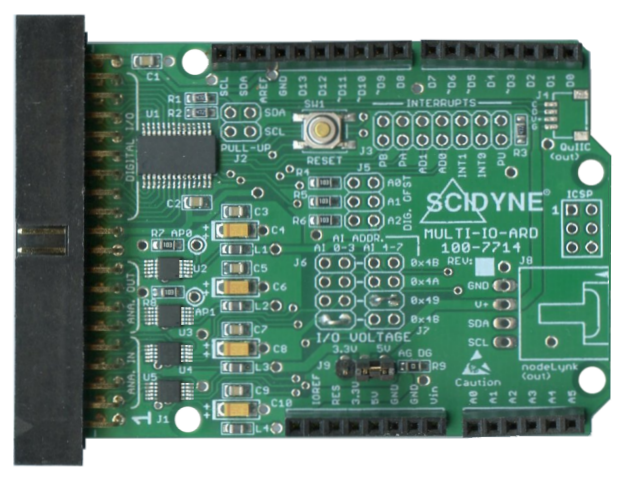
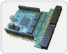
The MULTI-IO-ARD is an Arduino peripheral board designed to satisfy common analog and digital input/output requirements in a broad range of embedded applications. The hardware has been engineered to operate at either 3.3V or 5V making it compatible with common microcontroller boards such as Arduino Uno, Mega, Due, and other compatibles.
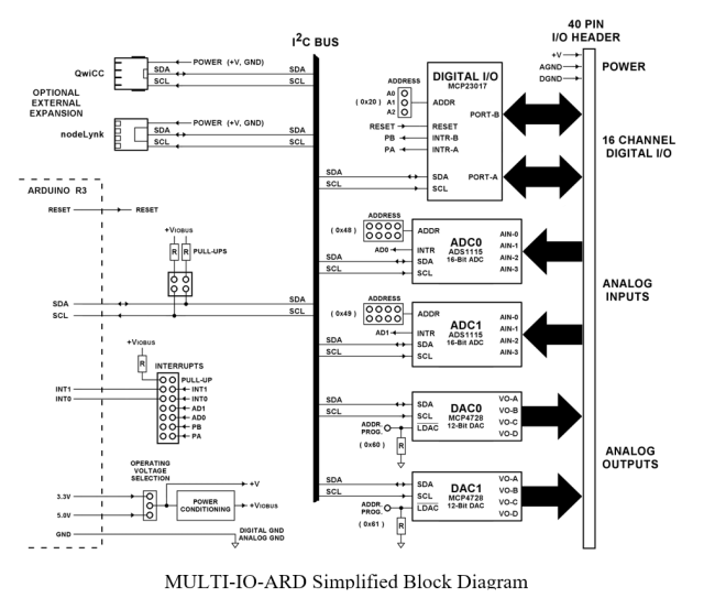
16 Digital Input / Output channels
An industry standard MCP23017 I/O Expander chip provides 16 non-isolated digital Input/Output channels across two 8-bit ports. This device is very versatile and offers flexible configurations, including software programmable channel directions and interrupt-driven change-of-state and pattern matching functions. Each channel features TTL/CMOS compatible signal levels and 25mA drive capability. In addition, software programmable weak pull-up resistors are available on any of the channels. This feature makes sensing open-collector, switches, and contact-closure type devices simple and straight-forward.
Eight Analog Inputs
Two ADS1115 Analog-to-Digital converter chips supply eight 16-bit analog inputs. The inputs are programmable as eight single-ended, four differential, or combinations of the two modes. A comparator feature can be used to detect under/over input voltage conditions.
Eight Analog Outputs
Two MCP4728 Digital-to-Analog chips are used to generate eight 12-bit analog outputs. Output values can be stored in EEPROM for rapid pre-set voltage levels after power up.
FEATURES
- Standard Arduino R3 hardware footprint
- Jumper selectable +3.3V or +5V operating voltage
- Low Power Requirement
- I2C interface, Up to 1.7Mbs
- Supports Open-Source libraries from Adafruit, SparkFun, and others
- Optional Qwiic and nodeLynk output connections
- 16 digital Input / Output channels
- MCP23017 Chip
- All channels are Bi-Directional
- Programmable Pull-Up resistors
- Change-of-State and Pattern matching interrupt capability
- Eight Analog Inputs
- Two ADS1115 ADC Chips
- 16-Bit resolution
- Input ranges from ±256 mV to ±6.144 Volts
- Single-Ended and Differential modes
- Comparator detects under/over voltage measurements
- Eight Analog Outputs
- Two MCP4728 DAC Chips
- 12-Bit resolution
- EEPROM for pre-set output voltages at Power-Up
DOCUMENTATION
- User's Reference Manual (multi-io-ard_manual.pdf)
- Example Software (multi-io-ard_demo.zip)
- MCP23017 I/O Expander (MCP23017_20001952C.pdf)
- ADS1115 16-Bit ADC (ads1113.pdf)
- MCP4728 12-Bit DAC (MCP4728-22187E.pdf)
SPECIFICATIONS
| Digital I/O | |||||||||
| General: | One MCP23017 chip provides 16 bi-directional I/O channels across two 8-Bit ports | ||||||||
|---|---|---|---|---|---|---|---|---|---|
| Output Current: | ±25mA max. per output. Total may be limited by hosts inability to supply enough current. | ||||||||
| Pull-Up Resistor: | 100KΩ, individually software enabled on each I/O channel | ||||||||
| Analog Inputs | |||||||||
| General: | Two ADS1115 ADC chips provide up to eight Single-Ended or four Differential analog inputs | ||||||||
| A/D Resolution: | 16-bit (1 in 65536, No Missing Codes) | ||||||||
| Input Range: | Software programmable: ±6.144V, ±4.096V, ±2.048V, ±1.024V, ±0.512, ±0.256V | ||||||||
| Input impedance: | 710KΩ minimum | ||||||||
| Nonlinearity: | ±1LSB | ||||||||
| Sampling Rate: | 8, 16, 32, 64, 128, 250, 475, 860 SPS | ||||||||
| Analog Outputs | |||||||||
| General: | Two MCP4728 DAC chips provide eight analog output channels | ||||||||
| D/A Resolution: | 12-bit (1 in 4096 of full scale) | ||||||||
| Output Ranges: | Using Internal Vref ( 2.048V )
Using External Vref ( VDD = VIOBUS )
| ||||||||
| Output Current: | ±25mA max. per output. Total may be limited by hosts inability to supply enough current. | ||||||||
| Settling Time: | 6μs max. to within ±0.5LSB of final value | ||||||||
| Nonlinearity: | Less than ±2LSB | ||||||||
| I2C Interface | |||||||||
| Software: | Uses standard Arduino I2C Wire library functions. Fully supports open-source software libraries like those from Adafruit and SparkFun. | ||||||||
| Addressing: |
| ||||||||
| Speed: | Standard (100kbps), Fast (400kbps), High Speed (1.7Mbps) | ||||||||
| Pull-Ups: | Optional jumper enabled 4.7KΩ on SDA and SCL signals | ||||||||
| Interrupt (Optional): | One Arduino interrupt, jumper selectable IRQ 1 or 2. Used by Analog-to-Digital converters and/or Digital I/O. Optional jumper enabled 4.7KΩ Pull-Up Resistor. | ||||||||
| Connections: | |||||||||
| I/O: | 40 Position IDC Ribbon Cable | ||||||||
| External Expansion: | 4 Position Qwiic (optional), 4 position nodeLynk (optional) | ||||||||
| Arduino: | Standard Arduino R3 Stack-Through allow multiple shields
| ||||||||
| Miscellaneous: | |||||||||
| Power Requirement: | Jumper selectable +3.3V or +5.0V. Power derived from Arduino host. | ||||||||
| Dimensions: | Standard Arduino R3 footprint and dimensions, Approx. 2.10"W x 3.00"L overall | ||||||||
| Environmental: | Operating temperature: -25°C to 65°C (Standard) Non-condensing relative humidity: 5% to 95% Compliance: RoHS, Lead-Free CA Residents: Warning - Prop 65 Info | ||||||||
| Product Origin: | Designed, Engineered, and Assembled in U.S.A. by SCIDYNE Corporation using domestic and foreign components. | ||||||||
You may also be interested in these products
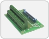
- Screw-Terminal Boards
- #100-7625
- Easily transition from IDC ribbon cable to field wiring