GPIO-104
General Purpose Analog and Digital I/O Module for PC/104 Bus
Stock Number:
- 100-7602
Budgetary Pricing:
- $327.00 / 001 - 009
- Contact us for More Quantity Discounts
Typical Lead-Time:
- Stock - 4wks

DESCRIPTION
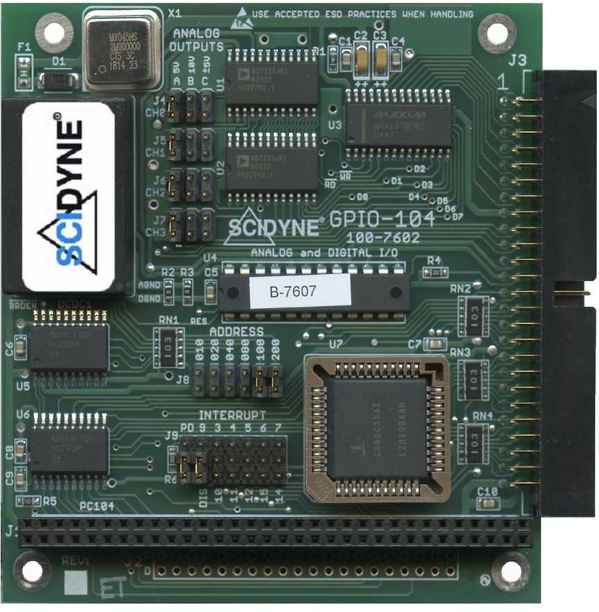
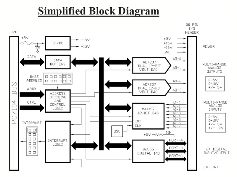
The GPIO-104 is an 8-bit analog and digital input/output module designed to satisfy a broad range of applications. Its generous assortment of functions and capabilities will, in many instances, make the GPIO-104 the only peripheral module required. It conforms to the PC/104 standard, operates on just +5V power, and uses a single 50-Position IDC header for all off-board I/O signal connections.
Analog Inputs
Eight 12-bit single-ended analog inputs are provided, each with software programmable input ranges of ±10V, ±5V, +5V, +10V. This capability effectively increases the dynamic range to 14-bits when employing software range-switching techniques. Input protection handles applied voltages up to ±16.5V and continues to function even when power is off. In addition, a fault condition on any input channel will not affect the operation of the remaining channels.
A special feature of the Analog-to-Digital Converter is its ability to allow the separate acquisition and conversion times be individually controlled by the user's software or automatically sequenced by the GPIO-104 hardware. Overall timing is precisely maintained by a crystal oscillator.
Analog-To-Digital conversions are initiated by writing a control byte which selects the input channel and sets its range along with other parameters. The host can determine when the conversion is complete using one of three methods: by simply waiting longer than the conversion time, by polling a status flag or by having the status flag interrupt the host when it becomes set. The resulting 12-bit value is read as two bytes in an 8+4 format.
Analog Outputs
The four 12-bit analog outputs are individually hardware programmable to provide one of three popular output ranges: ±5V, +5V, +10V. An on-board DC/DC converter enables the bipolar and +10V ranges to be achieved even though the GPIO-104 operates using only the PC/104 Bus +5V power supply.
The GPIO-104 includes the capability of having all the outputs update simultaneously by means of a single software write command. Those channels pre-loaded with new data will change, while the remaining channels maintain their previous output voltages glitch-free. This feature is particularly useful in applications which can not tolerate phasing errors between the outputs. The 12-bit data is loaded into the DACs using an 8+4 bit format.
Digital I/O
An industry standard 82C55 Programmable Peripheral Interface chip provides 24 digital channels across three 8-bit ports. This device offers very flexible configuration, including software programmable port directions and strobed handshaking. Each channel has a 10k pull-up resistor and defaults to logic "1" and input mode during system reset.
FEATURES
- Analog I/O and Digital I/O in a single low-cost module
- Eight 12-bit multi-range analog inputs (±10V, ±5V, +5V, +10V)
- Up to 100ksps throughput, self-timed or user-controlled acquisition
- Four 12-bit multi-range analog outputs (±5V, +5V, +10V)
- 24 digital Input/Output channels using familiar 82C55 chip
- Interrupts fully support sharing and access to all PC/104 bus IRQs
- Single +5 volt power requirement
DOCUMENTATION
- Product Bulletin (pb7602.pdf)
- User's Reference Manual (GPIO104.pdf)
- Example Software (gpio_ex1.zip)
- MAX197 - Multi-Range 12-Bit DAS (1042.pdf)
- AD7237 - Dual 12-Bit DACPORT (7237_47a.pdf)
- 82C55A - Programmable Peripheral Interface (fn2969.pdf)
SPECIFICATIONS
| Analog Inputs | |
| General: | One MAX197 DAS chip provides eight multi-range single-ended analog input channels |
|---|---|
| A/D Resolution: | 12-bit (1 in 4096 of full-scale), 14-bit effective dynamic range using software range-switching techniques |
| Input Range: | Each channel has software programmable input range: ±10V, ±5V, +5V or +10V |
| Overvoltage: | ±16.5V protection. A fault condition on any channel will not affect readings on other channels |
| Nonlinearity: | ±1LSB |
| Sampling: | 100,000 samples/sec max. (Host dependent), self-timed or user controlled acquisition |
| Analog Outputs | |
| General: | Two AD7237 chips provide four multi-range analog output channels. Supports simultaneous updates |
| D/A Resolution: | 12-bit (1 in 4096 of full scale) |
| Output Ranges: | Each channel has jumper selectable output range: ±5V, +5V or +10V |
| Output Current: | ±5mA max. per output |
| Settling Time: | 8μs max. to within ±1LSB of final value |
| Relative Accuracy: | ±1LSB |
| Nonlinearity: | Less than ±1LSB, guaranteed monotonic |
| Digital I/O | |
| General: | One 82C55 chip provides 24 digital I/O channels across three 8-Bit ports. Supports modes 0, 1 and 2 |
| Compatibility: | TTL/CMOS levels. Each channel is capable of sourcing or sinking 2.5mA, 10k pull-up on each channel |
| Miscellaneous | |
| Addressing: | 8-bit PC/104 bus. Jumper selectable for any 16 byte block in hosts I/O map, 0x00016 through 0x3f016 |
| Interrupt: | One interrupt, Jumper selectable IRQ 3,4,5,6,7,9, (10,11,12,14,15)* or Disable. Supports sharing. Used by Analog-to-Digital converter and positive level sensitive external interrupt. * Optional 20-Position J2/P2 stack-through connector required for upper IRQs |
| Power Requirement: | +5Vdc ±5% @ 340mA typical, unloaded outputs |
| Dimensions: | PC/104 compliant, 3.55"W x 3.77"L. 8-bit stack-through, optional 16-bit stack-through |
| Environmental: | Operating temperature: -25°C to 65°C (Standard) Non-condensing relative humidity: 5% to 95% Compliance: RoHS, Lead-Free CA Residents: Warning - Prop 65 Info |
| Product Origin: | Designed, Engineered, and Assembled in U.S.A. by SCIDYNE Corporation using domestic and foreign components. |
You may also be interested in these products
- Cable Assembly
- #115-7623/5018
- Flat ribbon cable with IDC connector on each end
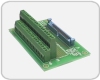
- Screw-Terminal Boards
- #100-7625
- Easily transition from IDC ribbon cable to field wiring